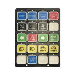
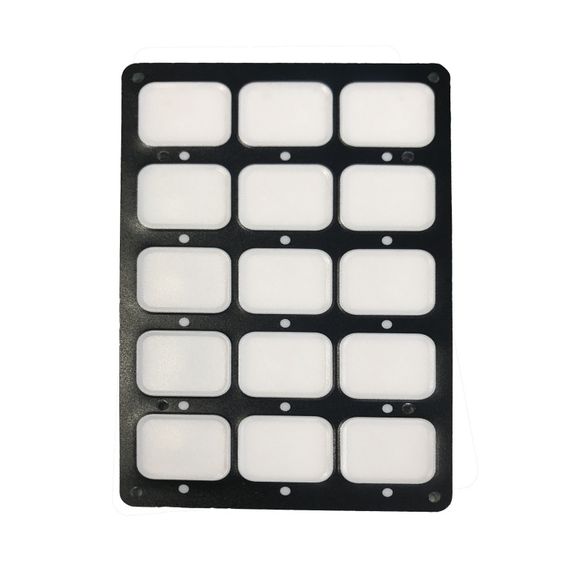


The XAP Technology SP15 & SP20 are 15- or 20-button CAN switch panels designed for rally, circuit racing, off-road and simulator projects. Their backlighting keeps the controls easy to read. LED feedback confirms that commands have been registered and makes the panels easier to use. Built-in maths channels allow users to create custom logic without changing the firmware, making each panel easier to adapt to the vehicle and its control strategy.
The SP15 & SP20 bring the controls drivers need together in a clear interface. XAP supplies a selection of coloured or black-and-white button icons, allowing the control layout to be tailored to the functions required by each project.
The panel receives information from the CAN network, processes and modifies it, and can transmit it again. Users can manage receive and transmit identifiers, control the LEDs using CAN signals and create their own logic with the built-in maths channels. This flexibility allows the configuration to evolve without modifying or expanding the switch panel.
XAP designed the SP15 & SP20 for rally, circuit racing and off-road vehicles, as well as simulator applications.
The SP15 & SP20 integrate into a CAN architecture through an Amphenol 451-02Y-1210-P50 connector. Their documented supply range is 8 to 19 V / 650 mA. CAN communication speed and termination can be selected to suit the network configuration.
The panel communicates over a CAN bus at up to 1 Mbit/s. XAP allows users to manage Rx and Tx identifiers, link LED behaviour to received signals, and use the built-in maths channels to process and retransmit CAN information.
| Specification | Value |
|---|---|
| Number of buttons | 15 (SP15) or 20 (SP20) |
| Backlighting | White backlighting |
| CAN communication | Up to 1 Mbit/s; selectable speed |
| CAN termination | Hardware-selectable |
| Power supply | 8 to 19 V / 650 mA |
| Ingress protection | IP65 |
| Weight | 200 g |
| Temperature range | −20 °C to 80 °C |
| Specification | Value |
|---|---|
| Dimensions taken from the illustration | 120 × 180.5 mm |
| Depth taken from the illustration | 25 mm |
| Option | Function |
|---|---|
| SP15 | 15-button CAN switch panel |
| SP20 | 20-button CAN switch panel |
| Button icons | Selection of coloured or black-and-white icons supplied with the panel |
| Pin | Signal | Connector position |
|---|---|---|
| 1 | CAN1_H | A |
| 2 | CAN1_L | B |
| 3 | EXT_USB_VBUS | C |
| 4 | EXT_USB_D+ | D |
| 5 | EXT_USB_D− | E |
| 6 | EXT_USB_GND | F |
| 7 | Not connected | G |
| 8 | Power supply (diagram label: “Alim”) | H |
| 9 | GND | J |
| 10 | GND | K |
| Reference | Description |
|---|---|
| PF0651 | SP15 — 15-button CAN switch panel |
| PF0686 | SP20 — 20-button CAN switch panel |
You might also like