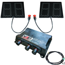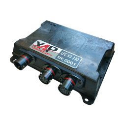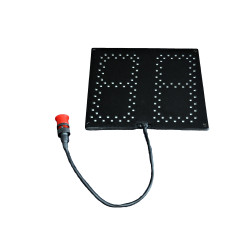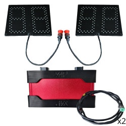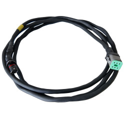
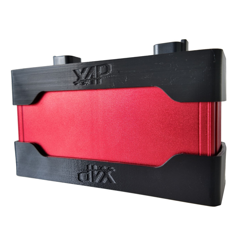


The XAP Technology LPC V2 LED panel controller is the central component of a position display system designed in particular for competition vehicles. It connects the vehicle CAN network to the LED panels to display race position, car number or system status information. Its architecture separates system communication from the dedicated panel link.
The LPC controller independently manages the left and right panels while centralising their power supply and connection interfaces. This arrangement helps teams build a display suited to the vehicle, the applicable regulations and the information that must remain immediately visible.
XAP configures the CAN protocol, panel identifiers and display behaviour to suit each project. The USB connection supports controller programming and integration into the vehicle’s electronic architecture. Depending on the selected functions, the configuration can cover race position, car number, timing, alerts, animations, RGB colours and brightness.
The system combines the LPC controller with XAP LPP-130 LED position panels. XAP can also support connector selection and harness adaptation. The product is intended for motorsport, aerospace, marine, industrial and special-purpose environments.
The LPC controller sits between the vehicle CAN network and the LED panels. XAP can adapt the CAN configuration and connections to the project. The installer must identify the controller version before wiring: the pinout below applies exclusively to the PF0856 LPC-230 V2 and must not be used for the LPC-330 V3.
The LPC accepts an 8 to 19 V supply and distributes the power required by the panels. It uses one CAN link for the system and a dedicated CAN link for the display, with separate connections to the right and left panels. The main LPC-230 V2 connector combines system CAN, five 12-bit analogue inputs, four digital inputs, USB, power supplies, grounds and a 5 V reference output.
| Specification | Value |
|---|---|
| Supply voltage | 8–19 V |
| Typical current | Approximately 650 mA for the complete system (LPC + 2 panels) |
| CAN interfaces | 2 × CAN 2.0B |
| CAN architecture | System CAN + dedicated panel CAN |
| Panel outputs | Independent left and right CAN channels |
| CAN protocol | Fully configurable |
| Configuration | USB connection and XAP DashEditor software |
| Temperature range | −20 °C to 80 °C |
| Pin | Signal | Function / note |
|---|---|---|
| 1 | CAN1 LOW | CAN 1, not terminated |
| 2 | CAN1 HIGH | CAN 1 |
| 3 | NC | Not connected |
| 4 | NC | Not connected |
| 5 | AN1 | 12-bit analogue input 1 |
| 6 | AN2 | 12-bit analogue input 2 |
| 7 | AN3 | 12-bit analogue input 3 |
| 8 | USB − | USB DATA − |
| 9 | USB + | USB DATA + |
| 10 | USB GND | USB ground |
| 11 | USB VBUS | USB power input |
| 12 | AN4 | 12-bit analogue input 4 |
| 13 | AN5 | 12-bit analogue input 5 |
| 14 | POWER SUPPLY | 12 V |
| 15 | POWER SUPPLY | 12 V |
| 16 | GND | Ground |
| 17 | GND | Ground |
| 18 | DIG4 | Digital input activated by connection to ground, 5 V max |
| 19 | DIG2 | Digital input activated by connection to ground, 5 V max |
| 20 | POWER SUPPLY | 12 V |
| 21 | POWER SUPPLY | 12 V |
| 22 | GND | Ground |
| 23 | GND | Ground |
| 24 | DIG3 | Digital input activated by connection to ground, 5 V max |
| 25 | DIG1 | Digital input activated by connection to ground, 5 V max |
| 26 | 5V OUT | 5 V reference for analogue sensors, up to 100 mA |
LPC-230 V2 CT1 connector: 26 positions, part number 6473423-2, AMP SUPERSEAL family, black.
| Pin | Signal | Function / note |
|---|---|---|
| 1 | Power supply | 12 V |
| 2 | 5V supply | 5 V logic supply (µP) |
| 3 | CAN HIGH | CAN communication, not terminated |
| 4 | CAN LOW | CAN communication |
| 5 | Side ID | Side identification |
| 6 | GND | Power ground |
LPC-230 V2 right CT2 connector: 6 positions, part number C-DT04-6P-CL06, DEUTSCH family, black.
| Pin | Signal | Function / note |
|---|---|---|
| 1 | Power supply | 12 V |
| 2 | 5V supply | 5 V logic supply (µP) |
| 3 | CAN HIGH | CAN communication, not terminated |
| 4 | CAN LOW | CAN communication |
| 5 | Side ID | Side identification |
| 6 | GND | Power ground |
LPC-230 V2 left CT3 connector: 6 positions, part number C-DT04-6P-CL06, DEUTSCH family, black.
| Reference | Description |
|---|---|
| PF0856 | LPC-230 V2 LED panel controller — product documented by the supplied pinout |
| PF0909 | LPC-330 V3 LED panel controller — product mentioned in the presentation |
| PF0855 | LPP-130 LED position panel — complementary system component |