XAP 4G IoT TELEMETRY MODULE – real-time vehicle data
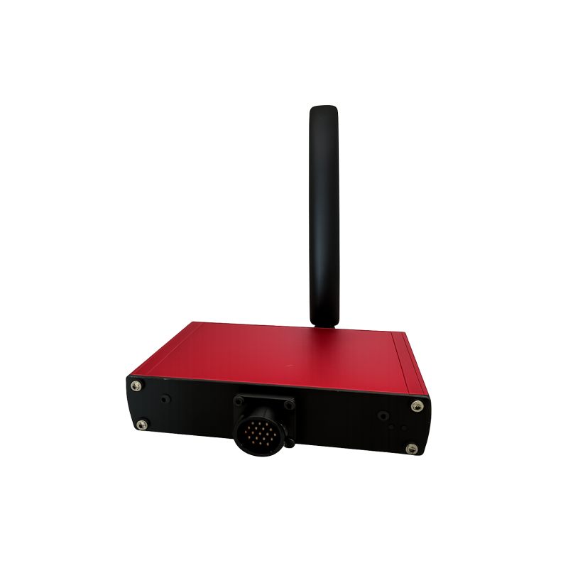
The XAP 4G IoT TELEMETRY MODULE is an embedded gateway designed for motorsport teams, R&D programmes and industrial applications. It acquires vehicle data over CAN and transmits it in real time through 4G/LTE networks at up to 20 Hz. Standalone operation, buffer memory for up to 24 hours and multiple interfaces make it easier to build a dependable, scalable telemetry chain.
The module enables engineers to remotely monitor critical parameters from ECUs, sensors and control systems. If the cellular network becomes unavailable, local storage continues recording the data and automatically synchronises it when the connection is restored. Timestamped data can therefore be used in real time or retrieved from the buffer to suit the project.
XAP designed this IoT gateway to operate as a standalone unit or as part of a complete XAP telemetry ecosystem. Its three CAN buses, Ethernet interface, USB port and Wi-Fi connection provide several integration paths. SIM card support simplifies cellular deployment, while bidirectional communication enables remote configuration.
Applications
The XAP 4G IoT TELEMETRY MODULE meets the vehicle monitoring requirements of motorsport, research and development validation, and embedded industrial system supervision. Its design addresses vibration, temperature variations and the electrical constraints encountered in these environments.
Key benefits
- Real-time data transmission over 4G/LTE networks at up to 20 Hz.
- Data acquisition over three CAN buses, including one eCAN bus.
- Buffer memory for up to 24 hours, with synchronisation after network recovery.
- Ethernet and USB 2.0 interfaces, with integrated Wi-Fi connectivity.
- SIM card support and MQTT, MQTTS, HTTP, HTTPS and REST protocols.
- Bidirectional communication for remote configuration, commands and updates.
Technical specifications and integration
The XAP 4G IoT TELEMETRY MODULE combines CAN acquisition, buffer storage and cellular transmission in an embedded enclosure. XAP can support the definition of the network architecture, connectivity and exchanges with the remote platform. Before installation, the integrator must validate the applicable supply range, wiring, protection, CAN bus termination and overall system compatibility.
Integration
The main J3 connector carries the power supply, three CAN interfaces, external USB and Ethernet. Cellular, Wi-Fi, Ethernet and USB interfaces make it possible to adapt the connection to the vehicle and its data infrastructure. The system also supports bidirectional voice communication for intercom use.
Telemetry module specifications
| Specification |
Value |
| Data acquisition |
CAN bus data acquisition |
| CAN interfaces |
3 CAN / CAN FD buses, including 1 eCAN |
| Ethernet |
Integrated Ethernet PHY |
| USB interface |
Yes |
| Status indicators |
RGB LEDs |
| Operating system |
RTX real-time operating system |
| Power supply |
8 to 70 V |
Data management and transmission
| Specification |
Value |
| Streaming rate |
Up to 20 Hz |
| Buffer memory |
Up to 24 hours |
| Transmission modes |
Real-time / buffered |
| Data integrity |
Timestamped data |
Confirmed electrical and environmental specifications
| Specification |
Value |
| Vehicle interface |
CAN bus |
| Power supply protection |
Reverse-polarity protection and filtering |
| Operating environment |
Motorsport / industrial environments, -10 °C to 80 °C |
| Installation |
Vehicle-embedded module |
Connectivity
| Interface |
Availability |
| Cellular |
4G / LTE |
| Wi-Fi |
Integrated |
| Ethernet |
Integrated |
| SIM |
SIM / eSIM support |
| GNSS |
GPS support |
Protocols and platform
| Function |
Protocols |
| Applications |
MQTT, MQTTS, HTTP, HTTPS, REST |
| Transmission |
TCP, UDP |
| Security and configuration |
TLS, SSL, JWT, Token, QoS configuration |
Audio and additional interfaces
| Specification |
Value |
| Audio codec |
16 / 24 / 32 bits |
| Uses |
Intercom and bidirectional voice communication |
| USB |
USB 2.0 |
Mechanical dimensions shown on the drawing
| Dimension |
Value |
| Thickness |
35 mm |
| Body width |
84 mm |
| Main length |
140 mm |
| Overall dimension with connectors |
110.85 mm |
J3 connector pinout – UTS014D19P
| Pin |
Contact |
Signal |
| 1 |
A |
USB_EXT_N |
| 2 |
B |
Power input |
| 3 |
C |
Power input |
| 4 |
D |
GND |
| 5 |
E |
GND |
| 6 |
F |
CAN1_N |
| 7 |
G |
CAN1_P |
| 8 |
H |
CAN3_N |
| 9 |
J |
CAN3_P |
| 10 |
K |
ETH_RD_N |
| 11 |
L |
USB_EXT_VBUS |
| 12 |
M |
USB_EXT_P |
| 13 |
N |
USB_EXT_GND |
| 14 |
P |
GND |
| 15 |
R |
ETH_TD_N |
| 16 |
S |
CAN2_N |
| 17 |
T |
CAN2_P |
| 18 |
U |
ETH_RD_P |
| 19 |
V |
ETH_TD_P |
XAP references
| Reference |
Description |
| PF0950 |
4G telemetry transmitter module |
Documentation
View the official telemetry module product page