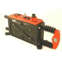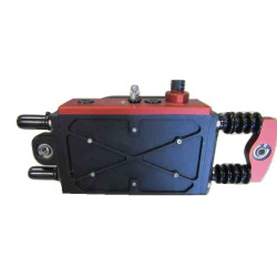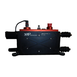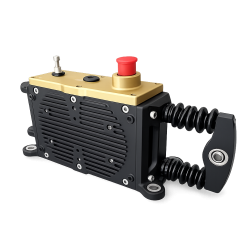
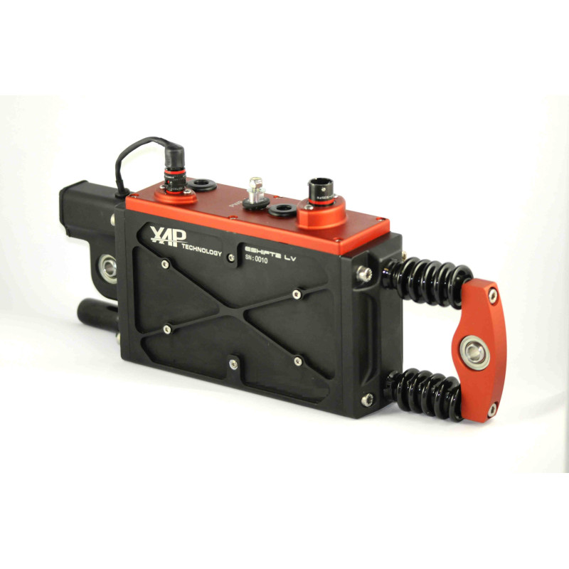


The XAP Technology E-SHIFT2 is a push-pull electromagnetic actuator designed to operate sequential gearboxes in motorsport. Its one-piece electromagnetic architecture replaces the pumps, seals, hoses and fluids used by pneumatic or hydraulic systems. This simplifies integration and reduces maintenance requirements while providing fast actuation, high force and flexible control options.
Moving-magnet technology and a magnetic spring move the actuator in both directions. The E-SHIFT2 delivers a typical gearshift time of 100 ms, with a maximum initial pushing force of 900 N and a maximum mid-stroke pushing force of 700 N.
XAP offers several configurations to suit the project, including ball-joint or threaded mounting, with or without a contactless shaft position sensor. The actuator can receive commands over CAN or through the CMD_UP, CMD_DOWN, CMD_LP and CMD_HP wired signals.
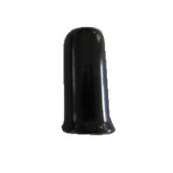
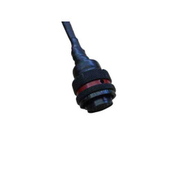
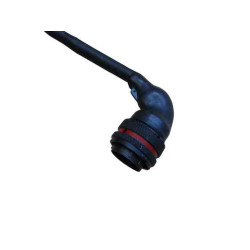
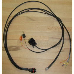
XAP can also assist with connector and wiring-loom selection to adapt the actuator to the vehicle’s electrical architecture, ECU and sequential gearbox.
The installer can control the actuator over CAN or use the CMD_UP, CMD_DOWN, CMD_LP and CMD_HP inputs. The product also reports diagnostics over CAN, while its architecture electrically separates power from the CAN network. Before installation, the installer must validate the wiring, electrical protection, CAN termination, ECU compatibility and gearshift strategy for the vehicle concerned.
| Specification | Value |
|---|---|
| Stroke | ±18 mm |
| Power consumption | Equivalent to 20 W for one gearshift every two seconds |
| Peak current | 100 A |
| Initial pushing force | 900 N max. |
| Mid-stroke pushing force | 700 N max. |
| Gearshift time | 100 ms typical |
| Diagnostics | CAN |
| Control | CAN or wired: CMD_UP, CMD_DOWN, CMD_LP, CMD_HP |
| Supply voltage | 9 to 18 V |
| Operating temperature | 100 °C max. |
| Weight | 4.2 to 5 kg |
| Feature | Purpose |
|---|---|
| Closed-loop control | Control of the standby position |
| Vibration mode | Assists disengagement and helps prevent dog-to-dog contact |
| Progressive push | Programmable control mode |
| Pin | Signal |
|---|---|
| 1 | CAN_L |
| 2 | CAN_H |
| 3 | USB_EXT_DP |
| 4 | CMD_HP |
| 5 | CMD_DOWN |
| 6 | CMD_UP |
| 7 | CMD_LP |
| 8 | GND |
| 9 | USB_EXT_VBUS |
| 10 | 12V_CMD |
| 11 | USB_EXT_DM |
| 12 | USB_EXT_GND |
| 13 | GND |
| Reference | Description |
|---|---|
| PF0731 | E-SHIFT2 LV3, ball-joint mounting, without position sensor |
| PF0732 | E-SHIFT2 LV3, threaded mounting, with position sensor |
| PF0733 | E-SHIFT2 LV3, ball-joint mounting, with position sensor |
| PF0734 | E-SHIFT2 LV3, threaded mounting, without position sensor |
| PF0003 | E-SHIFT2 98 |
You might also like