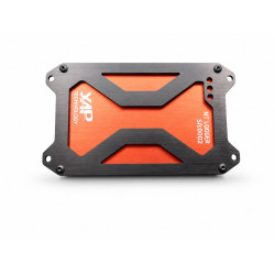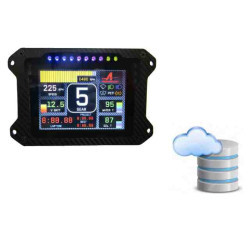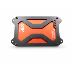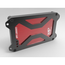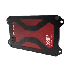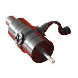
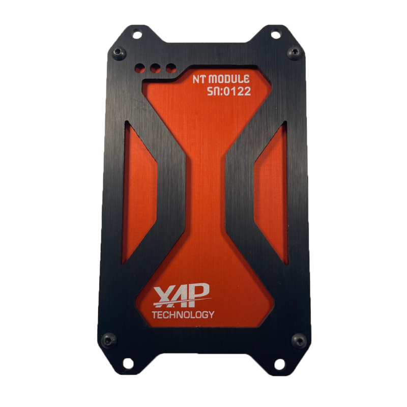


The XAP Technology NT CAN module is designed to centralise and process data from a competition vehicle. It supports teams competing in rallying, circuit racing, off-road events and other demanding disciplines. Its adaptable configuration provides a solution tailored to each project and the vehicle’s electronic architecture.
The NT CAN module communicates with a wide range of ECUs and CAN devices. XAP can provide predefined configurations or adapt the data table to the vehicle’s requirements. Users can also define their own parameters through the dedicated PC software available as an option.
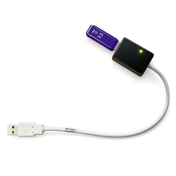
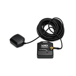
Depending on the selected configuration, XAP can equip the NT CAN module with a 20 Hz GPS and three accelerometers, real-time Wi-Fi communication, a performance analyser with predictive lap timing, a second CAN bus and a 37-way Autosport connector.
The NT CAN module supports data acquisition projects for rallying, circuit racing and off-road applications.
XAP assists with defining the data table, communications and options to adapt the NT CAN module to the vehicle architecture.
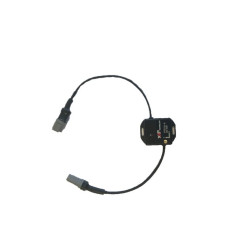
The NT CAN module operates from an 8 to 70 V power supply. The main J1 connector includes the power supply, CAN bus 1, USB, two analogue inputs, two digital inputs and a 5 V output. The optional 37-way J2 connector adds analogue and digital inputs, a second CAN bus, sensor power supplies and serial interfaces. XAP can prepare a specific configuration to simplify integration with the vehicle’s ECU and other devices.
| Specification | Value |
|---|---|
| Available channels | 1 to 400 |
| CAN communication | Up to two CAN buses, with or without termination |
| Power supply | 8 to 70 V / 450 mA |
| Operating temperature | −20 °C to 80 °C |
| Ingress protection | IP65 |
| Weight | 750 g |
| Specification | Value |
|---|---|
| Dimensions | 166 × 72 × 30 mm |
| Enclosure | Aluminium, with a customisable front panel |
| Connectors | Main 13-way Autosport connector; optional 37-way Autosport connector |
The following tables reproduce the signal designations from the supplied pinout diagram. J1 is identified as “8STA 2 10-35 PN”. J2 is identified as “8STA 2 14-35 SN”; this 37-way connector is optional. Signal names are retained exactly as shown on the diagram to avoid altering their electrical meaning.
| Pin | Signal |
|---|---|
| 1 | CAN1_L |
| 2 | CAN1_H |
| 3 | USB- |
| 4 | AGND |
| 5 | ANA1_IN |
| 6 | DIGI1HS_IN |
| 7 | DIGI2HS_IN |
| 8 | ANA2_IN |
| 9 | 5VOUT1 |
| 10 | Alim |
| 11 | GND |
| 12 | USB_PWR |
| 13 | USB+ |
| 14 | To be confirmed — “FIX” mark on the diagram |
| Pin | Signal |
|---|---|
| 1 | ANA1_IN |
| 2 | ANA2_IN |
| 3 | ANA3_IN |
| 4 | ANA4_IN |
| 5 | ANA5_IN |
| 6 | ANA6_IN |
| 7 | ANA7_IN |
| 8 | ANA8_IN |
| 9 | ANA9_IN |
| 10 | ANA10_IN |
| 11 | ANA11_IN |
| 12 | ANA12_IN |
| 13 | ANA13_IN |
| 14 | 5VOUT1 |
| 15 | 5VOUT1 |
| 16 | 5VOUT2 |
| 17 | 5VOUT2 |
| 18 | Alim_OUT1 |
| 19 | Alim_OUT2 |
| 20 | DIGI3HS_IN |
| 21 | DIGI4HS_IN |
| 22 | DIGI5_IN |
| 23 | DIGI6_IN |
| 24 | DIGI7_IN |
| 25 | RX232_IN |
| 26 | CAN2_H |
| 27 | CAN2_L |
| 28 | TX_LIN |
| 29 | GND |
| 30 | GND |
| 31 | AGND |
| 32 | AGND |
| 33 | AGND |
| 34 | AGND |
| 35 | AGND |
| 36 | AGND |
| 37 | AGND |
| Reference | Description |
|---|---|
| PF0538 | Standard NT Logger |
| PF0539 | Standard NT Logger + GPS |
| PF0541 | Standard NT Logger + Wi-Fi |
| PF0540 | Standard NT Logger + 37-way connector |
| PF0546 | Standard NT Logger + 37-way connector + GPS + Wi-Fi |
| PF0589 | CAN module without logger + 37-way connector |
You might also like