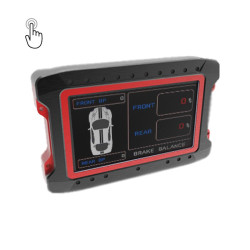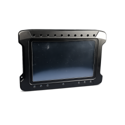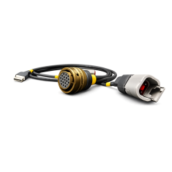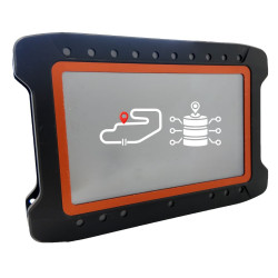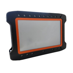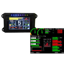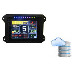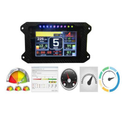
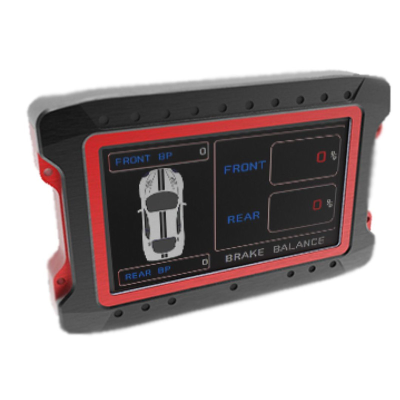

The XAP Technology DASH NT7 is a 7-inch dashboard for test-bench supervision, endurance programmes, motorsport and industrial systems. It displays, logs and controls multiple parameters through one interface. Configurable CAN architecture, numerous inputs, and touch and connectivity options allow XAP to tailor the control station to a complex installation.
The DASH NT7 displays multiple real-time channels, plots live graphs and manages alarms or system modes. Its 800 × 480 px TFT, ambient light sensor and 16 programmable RGB LEDs keep essential states readable by day or night.
DashEditor lets users build a screen configuration from scratch or adapt an existing setup. Built-in maths and virtual channels enhance received data, while bidirectional communication can send commands to connected modules when supported by the system configuration.
The NT7 suits engine and vehicle test benches, simulation, industrial monitoring, motorsport, IoT and telemetry platforms. XAP offers self-supporting enclosure and enclosure-free versions for panel or rack integration, plus GPS, logging, touchscreen and extended connectivity options.
The DASH NT7 operates from 8 to 70 V and communicates over CAN and USB. XAP can tailor the configuration, supply a start or table loom and select the options required for a bench or vehicle. The installer should then confirm pinout, power protection, CAN termination and interfaces against the documentation for the selected variant.
The DASH NT7 uses one main 19-way connector and can receive two 32-way connectors. The first 32-way connector adds 14 analogue inputs, 10 Mb Ethernet, 1 LIN, 1 RS485 and 1 RS232. The optional second connector adds 14 analogue inputs and 12 digital inputs.
With all three connectors and the full hardware option, the DASH NT7 provides 32 analogue 0–5 V inputs, 12 digital inputs, 2 CAN buses, 10 Mb Ethernet, 1 RS485, 1 RS232 and 1 LIN. PF0678 and PF0692 combine GPS with extended connectivity; PF0691 and PF0692 are supplied without an enclosure. The PF0698 touchscreen option turns the display into a control interface.
| Specification | Value |
|---|---|
| Power supply | 8 to 70 V |
| Current consumption | 500 mA nominal; 1.8 A maximum |
| Display / resolution | 7-inch sunlight-readable TFT; 800 × 480 px |
| Ambient light sensor | Yes, day/night mode available |
| RPM / alert / diagnostic LEDs | 16 programmable RGB LEDs |
| CAN communication | 2 CAN buses |
| PC interface | USB |
| Analogue inputs | Up to 32 inputs, 0–5 V, with the full hardware option |
| Digital inputs | Up to 12 with the full hardware option |
| Extended interfaces | 10 Mb Ethernet, 1 LIN, 1 RS485 and 1 RS232 with extended connectivity |
| Compatibility | DBC-configurable CAN for multiple ECUs |
| Electromagnetic compatibility | Automotive EMC standard |
| Specification | Value |
|---|---|
| Dimensions | 210 × 145 × 58 mm |
| Weight | 420 g without enclosure |
| Ingress protection | IP65 with the described enclosure |
| Operating temperature | −20 °C to 80 °C |
| Shock and vibration resistance | > 30 G RMS |
| Enclosure | Self-supporting; enclosure-free version available for panel or rack integration |
| Option | Function |
|---|---|
| GPS and synchronisation | 20 Hz GPS; enables Performance Analyser and Tripmaster depending on configuration |
| Data logging | 8 GB data logger with CSV export |
| Full hardware option | Three connectors in total: 32 analogue 0–5 V inputs, 12 digital inputs, 2 CAN buses, 10 Mb Ethernet, 1 RS485, 1 RS232 and 1 LIN |
| Touchscreen | Integrated touch interface, reference PF0698 |
| Race analysis | Performance Analyser with GPS; odometer / Tripmaster |
| Looms | Start loom and table loom |
| Configuration | Custom configuration and PC tool |
| Simulation | Compatible with simulators |
The tables below reproduce the pinout supplied by XAP. The 32-way J6 connector is the optional extension. Installers should use this pinout together with the electrical documentation for the selected variant.
| Pin | Signal |
|---|---|
| A | CAN1_L |
| B | CAN1_H |
| C | EXT_USB_D− |
| D | EXT_USB_GND |
| E | ANA1 |
| F | WHEEL1 |
| G | WHEEL2 |
| H | ANA2 |
| J | 5V_OUT1 |
| K | +14VIn |
| L | GND |
| M | EXT_USB_VBUS |
| N | EXT_USB_D+ |
| P | CAN2_H |
| R | CAN2_L |
| S | ANA3 |
| T | ANA4 |
| U | WHEEL3 |
| V | WHEEL4 |
| Pin | Signal |
|---|---|
| A | ANA5 |
| B | ANA6 |
| C | ANA7 |
| D | ANA8 |
| E | ANA9 |
| F | ANA10 |
| G | ANA11 |
| H | ANA12 |
| J | ANA13 |
| K | ANA14 |
| L | ANA15 |
| M | ANA16 |
| N | ANA17 |
| P | ANA18 |
| R | ANA_USB_ID_OUT |
| S | ETH_TD+ |
| T | ETH_TD− |
| U | ETH_RD+ |
| V | ETH_RD− |
| W | LIN |
| X | RS485_A |
| Y | RS485_B |
| Z | RS232_RX |
| a | RS232_TX |
| b | +5V_OUT3 |
| c | +5V_OUT3 |
| d | +5V_OUT2 |
| e | +5V_OUT2 |
| f | +5V_OUT2 |
| g | GND |
| h | GND |
| j | GND |
| Pin | Signal |
|---|---|
| A | ANA19 |
| B | ANA20 |
| C | ANA21 |
| D | ANA22 |
| E | ANA23 |
| F | ANA24 |
| G | ANA25 |
| H | ANA26 |
| J | ANA27 |
| K | ANA28 |
| L | ANA29 |
| M | ANA30 |
| N | ANA31 |
| P | ANA32 |
| R | DIG1 |
| S | DIG2 |
| T | DIG3 |
| U | DIG4 |
| V | DIG5 |
| W | DIG6 |
| X | DIG7 |
| Y | DIG8 |
| Z | DIG9 |
| a | DIG10 |
| b | DIG11 |
| c | DIG12 |
| d | GND |
| e | GND |
| f | GND |
| g | GND |
| h | GND |
| j | GND |
| Reference | Description |
|---|---|
| PF0679 | DASH NT7 standard |
| PF0678 | DASH NT7 with GPS and extended connectivity |
| PF0691 | DASH NT7 standard without enclosure |
| PF0692 | DASH NT7 with GPS and extended connectivity, without enclosure |
| PF0698 | Touchscreen option |
| PF0339 | Data logging option |
| PF0436 | Performance Analyser option |
| PF0587 | Tripmaster option |
You might also like