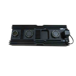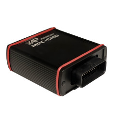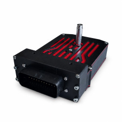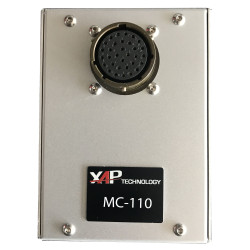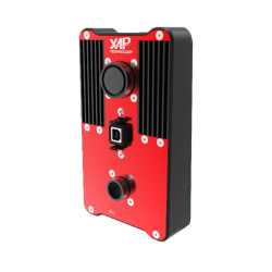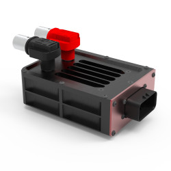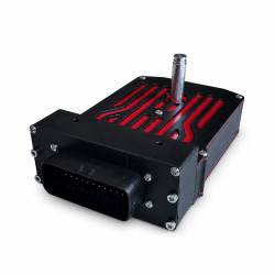

The XAP Technology RTCM is an electronic power distribution module for motorsport electrical systems and demanding vehicle electronics projects. It replaces conventional relays and fuses with protected, configurable outputs, helping to simplify the wiring harness, reduce weight and improve diagnostics. The supplied RTCM conf software lets users tailor current thresholds and output behaviour to the requirements of each vehicle.
The RTCM protects each connected device individually through configurable current thresholds. XAP can therefore tailor the power distribution logic to the pumps, fans, lights, ECUs and other loads installed in the vehicle, without the fixed operating constraints of a conventional relay-and-fuse wiring harness.
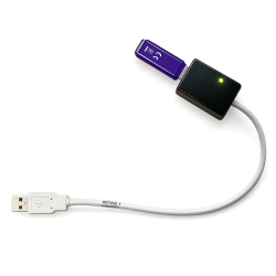
RTCM conf PC software provides control over parameters including overcurrent blanking time, maximum current, continuous or flashing operation, latched or timed commands, and the automatic reset strategy following an overcurrent event. Output status feedback and current-consumption monitoring make circuit supervision and fault-finding easier.
CAN communication allows the RTCM to interface with vehicle equipment and supports networks of multiple modules operating in master/slave or independent mode. XAP can assist with configuration, connectors and wiring-harness design to adapt the product to the project architecture.
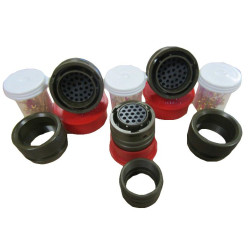
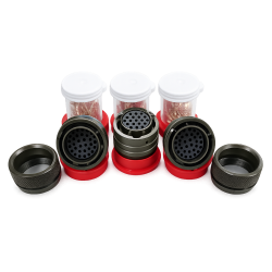
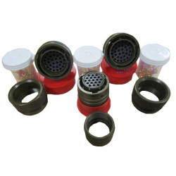
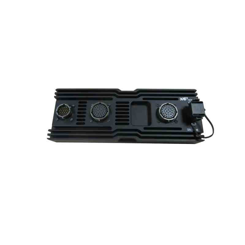
The RTCM uses three military-grade Amphenol connectors. Wiring must follow the physical pin assignments below, the harness current ratings and the installation’s main protection requirements. XAP can supply the connectors, tailor the wiring harness and assist with CAN network and output-strategy configuration.
Connector C1 carries the battery supply, power grounds and external relay control. Connectors C2 and C3 carry the HP and MP outputs, seven digital inputs, two CAN buses, main-relay commands and two analogue inputs. The RTCM also manages the main battery relay.
Before power-up, XAP recommends checking conductor sizing, upstream protection, CAN termination, the pinout of connected equipment and the RTCM conf setup. This description does not replace the installation manual or final wiring-harness validation.
| Specification | Value |
|---|---|
| HP outputs | 12 outputs; 15 to 50 A peak; 8 thresholds |
| MP outputs | 22 outputs; 7.5 to 25 A peak; 8 thresholds |
| Programmable delay monitoring | Programmable from 0.15 to 155 ms; 4 thresholds for each MP and HP output |
| Communication | 2 CAN buses |
| Digital inputs | 7 digital inputs with 5 V pull-up |
| Analogue inputs | 2 inputs, 0–5 V |
| Main relay management | Yes; main battery relay up to 300 A and master cut-off control |
| Ingress protection | IP65 |
| Operating temperature | −10 °C to 100 °C |
| Enclosure | Solid aluminium |
| Configuration software | RTCM conf supplied |
| Connector | Amphenol reference | Number of pins |
|---|---|---|
| C1 | 451 06RT 14-19 S50 | 19 |
| C2 | 451 06RT 18-32 P50 | 32 |
| C3 | 451 06RT 18-32 PW50 | 32 |
| Pin | Signal | Function |
|---|---|---|
| A | 12V IN | 12 V battery power input |
| B | 12V IN | 12 V battery power input |
| C | 12V IN | 12 V battery power input |
| D | 12V IN | 12 V battery power input |
| E | 12V IN | 12 V battery power input |
| F | RELAY EXT | External relay activation to GND |
| G | 12V IN | 12 V battery power input |
| H | 12V IN | 12 V battery power input |
| J | 12V IN | 12 V battery power input |
| K | 12V IN | 12 V battery power input |
| L | 12V IN | 12 V battery power input |
| M | 12V IN | 12 V battery power input |
| N | 12V IN | 12 V battery power input |
| P | 12V IN | 12 V battery power input |
| R | 12V IN | 12 V battery power input |
| S | 12V IN | 12 V battery power input |
| T | 12V IN | 12 V battery power input |
| U | GND | Ground |
| V | GND | Ground |
| Pin | Signal | Function |
|---|---|---|
| A | MP11 | MP11 output |
| B | MP10 | MP10 output |
| C | MP09 | MP09 output |
| D | MP08 | MP08 output |
| E | MP07 | MP07 output |
| F | MP06 | MP06 output |
| G | MP05 | MP05 output |
| H | MP04 | MP04 output |
| J | MP03 | MP03 output |
| K | MP02 | MP02 output |
| L | MP14 | MP14 output |
| M | MP13 | MP13 output |
| N | MP12 | MP12 output |
| P | HP03 | HP03 output |
| R | HP03 | HP03 output |
| S | CMD IN 4 | Digital input 4, 5 V pull-up |
| T | MP01 | MP01 output |
| U | CAN2_HIGH | CAN 2 High |
| V | HP02 | HP02 output |
| W | HP02 | HP02 output |
| X | CMD IN 3 | Digital input 3, 5 V pull-up |
| Y | CMD IN 5 | Digital input 5, 5 V pull-up |
| Z | CMD IN 1 | Digital input 1, 5 V pull-up |
| a | MASTER OFF | Momentary switch-to-ground command: OFF |
| b | CAN 1 LOW | CAN 1 Low |
| c | CAN 1 HIGH | CAN 1 High |
| d | MASTER ON | Momentary switch-to-ground command: ON |
| e | CMD IN 2 | Digital input 2, 5 V pull-up |
| f | MP15 | MP15 output |
| g | HP01 | HP01 output |
| h | HP01 | HP01 output |
| j | CAN2_LOW | CAN 2 Low |
| Pin | Signal | Function |
|---|---|---|
| A | AGND | Analogue ground |
| B | MP16 | MP16 output |
| C | HP11 | HP11 output |
| D | HP11 | HP11 output |
| E | HP10 | HP10 output |
| F | HP10 | HP10 output |
| G | HP09 | HP09 output |
| H | HP09 | HP09 output |
| J | HP05 | HP05 output |
| K | HP05 | HP05 output |
| L | HP06 | HP06 output |
| M | HP06 | HP06 output |
| N | HP07 | HP07 output |
| P | HP07 | HP07 output |
| R | HP08 | HP08 output |
| S | HP08 | HP08 output |
| T | MP17 | MP17 output |
| U | ANA 1 | Analogue input 1, 0–5 V |
| V | CMD IN 10 | Digital input 10, 5 V pull-up |
| W | ANA 2 | Analogue input 2, 0–5 V |
| X | MP22 | MP22 output |
| Y | MP21 | MP21 output |
| Z | HP04 | HP04 output |
| a | HP04 | HP04 output |
| b | CMD IN 9 | Digital input 9, 5 V pull-up |
| c | MP20 | MP20 output |
| d | MP19 | MP19 output |
| e | MP18 | MP18 output |
| f | HP12 | HP12 output |
| g | HP12 | HP12 output |
| h | HP12 | HP12 output |
| j | HP12 | HP12 output |
| Reference | Description |
|---|---|
| PF0570-A | RTCM-231 — Full Digital version |
| PF0316-B | RTCM-230 — 2 CAN version |
Download the XAP RTCM platform datasheet. For final configuration and wiring-harness validation, contact XAP Technology with reference PF0316-B and the product hardware version.
You might also like