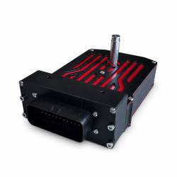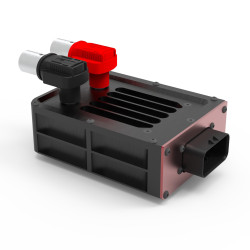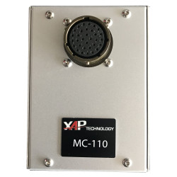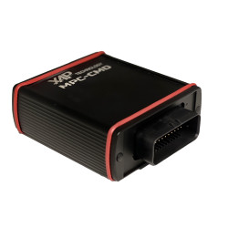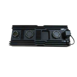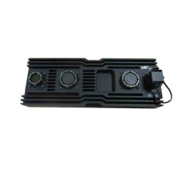
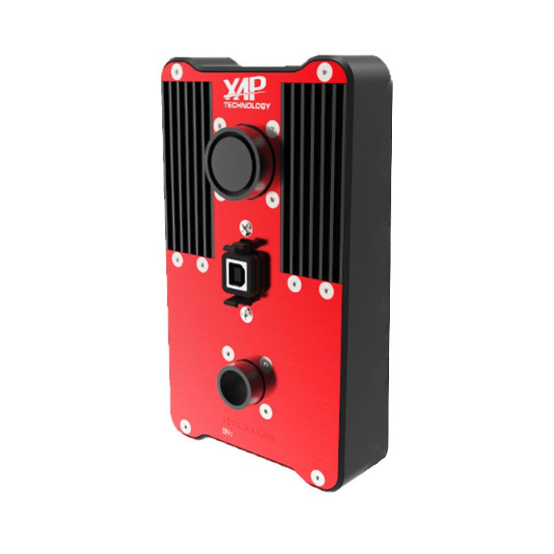


The XAP Technology RTCX-120 Powerbox is an electrical power distribution system for competition vehicles and demanding embedded architectures. It replaces conventional fuses and relays with protected electronic outputs configured through the supplied RTCMconf software. Users can tailor current thresholds and control strategies to their project while monitoring output status and current consumption.
The RTCX-120 simplifies wiring loom design and adds flexibility to the electrical architecture. It can control equipment such as windscreen wipers, lights and fuel pumps, as well as flashing functions.
RTCMconf allows users to configure current thresholds, monitoring delays, continuous or alternating operation, latched or delayed commands, and the automatic reset strategy following an overcurrent event. XAP can support Powerbox integration with its displays, data acquisition systems, multiplexed keypads and steering wheels via CAN, according to the project architecture.
For distributed architectures, multiple RTCX units can communicate over the CAN network in master/slave mode or operate independently. The RTCX-120 also manages the main battery relay.
The RTCX-120 centralises the control and protection of electrical equipment. The installer configures each function in RTCMconf, connects the commands and outputs to the connectors identified below, then validates the thresholds, protection settings, CAN network and cut-off strategy for the vehicle.
The Powerbox provides one CAN interface and seven inputs that RTCMconf can configure as digital or analogue. HP outputs cover a 15 to 50 A range with eight thresholds, while MP outputs cover a 7.5 to 25 A range with eight thresholds. The monitoring delay for each MP and HP output can be set from 0.15 to 155 ms using four thresholds.
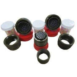
The J2 and J3 interfaces use Amphenol 451-series connectors. XAP recommends validating the final wiring, protection settings, CAN termination and equipment compatibility before applying power.
| Specification | Value |
|---|---|
| HP outputs | 2 outputs; 15 to 50 A; 8 thresholds |
| MP outputs | 16 outputs; 7.5 to 25 A; 8 thresholds |
| Monitoring delay | Programmable from 0.15 to 155 ms; 4 thresholds for each MP and HP output |
| Inputs | 7 inputs configurable as digital or analogue through RTCMconf |
| Communication bus | 1 × CAN |
| Battery management | Main battery relay management |
| Operating temperature | −10 °C to 100 °C |
| Protection rating | IP67 |
| Enclosure | Solid aluminium |
| Connectors | Military 451/851 and AS-series connectors |
| Weight | 700 g |
| Pin | Signal |
|---|---|
| 1 | 12 V power supply |
| 2 | GND |
| 3 | CMD_RELAY_EXT |
| 4 | Not specified |
| 5 | 12 V power supply |
| 6 | 12 V power supply |
| 7 | 12 V power supply |
| 8 | 12 V power supply |
| 9 | 12 V power supply |
| 10 | 12 V power supply |
| Pin | Signal |
|---|---|
| 1 | OUT_MP_11 |
| 2 | OUT_MP_10 |
| 3 | OUT_MP_9 |
| 4 | OUT_MP_8 |
| 5 | OUT_MP_7 |
| 6 | OUT_MP_6 |
| 7 | OUT_MP_5 |
| 8 | OUT_MP_4 |
| 9 | OUT_MP_3 |
| 10 | OUT_MP_2 |
| 11 | OUT_MP_14 |
| 12 | OUT_MP_13 |
| 13 | OUT_MP_12 |
| 14 | OUT_HP_2 |
| 15 | OUT_HP_2 |
| 16 | CMD_IN_4 |
| 17 | OUT_MP_1 |
| 18 | CMD_IN_7 |
| 19 | OUT_HP_1 |
| 20 | OUT_HP_1 |
| 21 | CMD_IN_3 |
| 22 | CMD_IN_5 |
| 23 | CMD_IN_1 |
| 24 | SWITCH_OFF |
| 25 | CAN− |
| 26 | CAN+ |
| 27 | SWITCH_ON |
| 28 | CMD_IN_2 |
| 29 | OUT_MP_15 |
| 30 | OUT_MP_16 |
| 31 | OUT_MP_16 |
| 32 | CMD_IN_6 |
| Reference | Description |
|---|---|
| PF0581 | RTCX-120 Powerbox |
You might also like