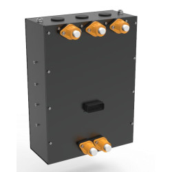
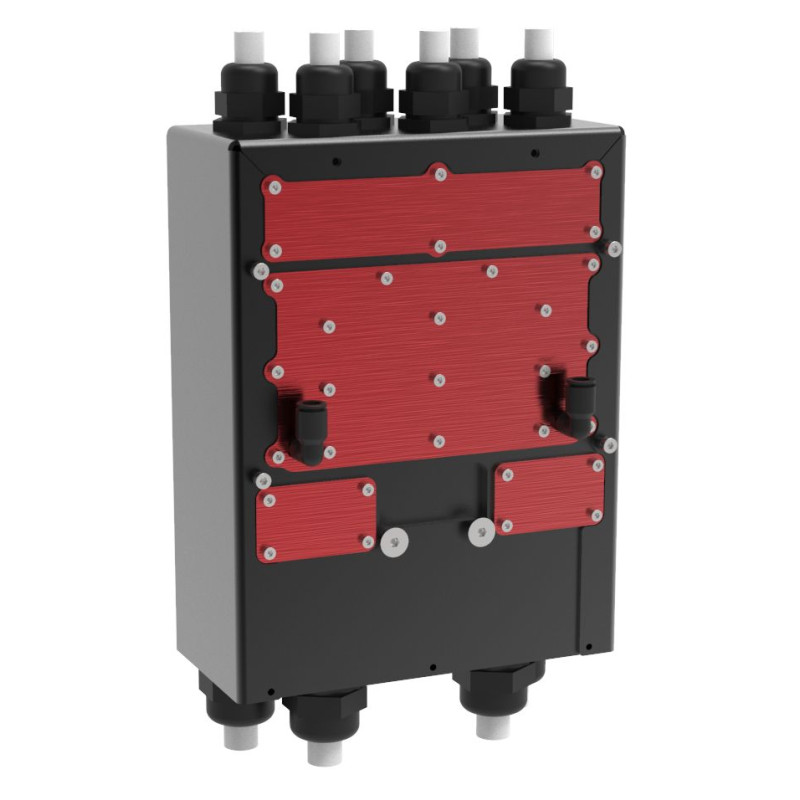


The XAP Technology LVC30 is a low-voltage inverter designed for electric retrofit, hybrid powertrain, industrial vehicle, marine and aerospace projects. It can control one 30 kW three-phase or six-phase motor, or two 15 kW three-phase motors. Its 12 to 80 V DC operating range, liquid cooling and embedded dynamic control help engineers create compact, configurable and scalable electric powertrains.
By combining two controllers in one enclosure, the LVC30 adapts its control architecture to the motor and the project. It delivers 30 kW continuously at 60 V and up to 60 kW peak at 60 V for short-duration operation. Its Flux Oriented Control (FOC) is designed to optimise the efficiency and dynamic response of internal- or external-rotor permanent-magnet PMSM or BLDC motors.
The embedded XAP Dynamic Control System enables real-time parameter adjustment and mapping with three access levels: basic, standard and expert. The associated PC software allows engineers to calibrate physical values and fine-tune powertrain behaviour. The additional inputs and outputs also allow the LVC30 to run application logic as an embedded controller.
The LVC30 supports several position and speed feedback technologies: Hall sensors, resolver, sin/cos, digital SSI and digital encoder. This flexibility, combined with two independent CAN FD buses and an isolated USB connection for setup and diagnostics, helps system integrators build an architecture suited to their application.
XAP designed the LVC30 for low-voltage electric conversions, hybrid systems, industrial vehicles, marine systems and aerospace applications. The exact combination of motor, sensors, battery, cooling and wiring must be defined according to the project requirements.
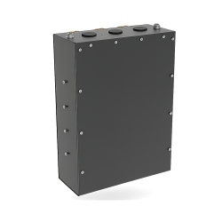
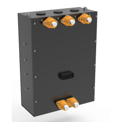
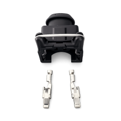
XAP combines motor control, sensor interfaces and application control functions in a 302 × 220 × 127 mm enclosure. The 35-way J1 signal connector brings together both CAN buses, the isolated USB interface, sensor feedback and auxiliary commands. System integrators can calibrate the unit through the PC software and adapt its operating logic to the vehicle or machine architecture.
The LVC30 uses four 70 mm² conductors for the DC battery connection and six 35 mm² conductors for the motor phases. Four 10 mm push-fit ports provide the inlet and outlet connections for the liquid-cooling circuit. An air-cooled-only version is available as an option.
Before power-up, the system integrator must validate the motor and sensor selection, cable and protection sizing, cooling circuit, harness pinout, and CAN configuration and termination. This validation must refer to the installation documentation applicable to the supplied version.
| Specification | Value |
|---|---|
| Nominal voltage | 60 V DC |
| Voltage range | 12 to 80 V DC |
| Logic power supply | 8 to 75 V DC |
| Continuous power | 30 kW at 60 V |
| Peak power | 60 kW at 60 V — short-duration operation |
| Continuous current | 500 A DC per phase/power channel |
| Sustained high current | 600 A DC for more than one minute |
| Transient peak | 1000 A DC — acceleration or transient load |
| Efficiency | 95% |
| Specification | Value |
|---|---|
| Drive configurations | 1 × 30 kW three-phase motor; 1 × 30 kW six-phase motor; 2 × 15 kW three-phase motors |
| Motor types | Permanent-magnet PMSM / BLDC motors with internal or external rotor |
| Control | Flux Oriented Control (FOC); embedded XAP Dynamic Control System with real-time mapping |
| Calibration access levels | Basic, standard and expert |
| Position/speed sensors | Hall, resolver, sin/cos, digital SSI and digital encoder |
| Interface | Function |
|---|---|
| CAN | 2 × CAN FD with independent bit rates |
| USB | 1 × isolated USB for setup and diagnostics |
| Inputs/outputs | 8 analogue inputs; 5 digital inputs; 2 × 5 A high-side PWM outputs |
| Embedded control function | The additional inputs and outputs allow the unit to run application logic |
| Logic safety function | Logic Power Latched to establish a secured mode before complete shutdown |
| PC software | Physical-value calibration and performance fine-tuning |
| Specification | Value |
|---|---|
| Cooling | Optimised liquid cooling; air-cooled-only version available as an option |
| Cooling ports | 4 × 10 mm push-fit ports — inlet/outlet |
| Ingress protection | IP65 |
| Operating temperature | −40 °C to +85 °C |
| Specification | Value |
|---|---|
| Overall dimensions | 302 × 220 × 127 mm |
| Weight | 5 kg |
| DC battery connection | 4 × 70 mm² |
| Motor connection | 6 × 35 mm² |
| Signal/command connector | 35-way AMPSEAL — TE 1-776230-1 |
| Pin | Signal shown in the diagram |
|---|---|
| 1 | CAN1 Ext P |
| 2 | CAN1 Ext N |
| 3 | CAN2 Ext P |
| 4 | CAN2 Ext N |
| 5 | EXT USB VBUS |
| 6 | EXT USB D_N |
| 7 | EXT USB D_P |
| 8 | EXT USB GND |
| 9 | MOT1 HALL1 |
| 10 | MOT1 HALL2 |
| 11 | MOT1 HALL3 |
| 12 | MP2 |
| 13 | GND |
| 14 | GND |
| 15 | ANA_CPU |
| 16 | ANA_CPU |
| 17 | ANA_IN1/MOT2_HALL1 |
| 18 | ANA_IN2/MOT2_HALL2 |
| 19 | ANA_IN3/MOT2_HALL3 |
| 20 | ANA_IN4 |
| 21 | GND |
| 22 | GND |
| 23 | MP1 |
| 24 | ANA_IN5 |
| 25 | RES_EXC |
| 26 | RES_/EXC |
| 27 | COS_uC_P |
| 28 | COS_uC_N |
| 29 | SIN_uC_P |
| 30 | SIN_uC_N |
| 31 | ANA_IN6 |
| 32 | ANA_IN7 |
| 33 | ANA_IN8 |
| 34 | Alim_CMD |
| 35 | Alim_CMD |
| Reference | Description |
|---|---|
| PF0839 | LVC30 INVERTER 60V - 30 KW |
You might also like