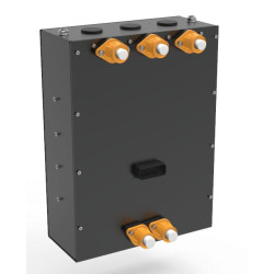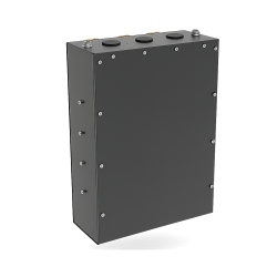
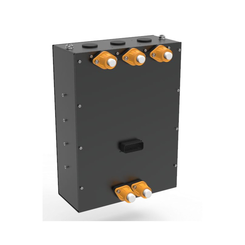


XAP Technology's HVC-200 is a 400 V high-voltage motor controller for demanding traction architectures, from retrofit vehicles and electric utility vehicles to development platforms. Its 200 kW continuous power rating, liquid cooling system and Motor-Editor calibration tool support compact integration and progressive setup throughout the project.
The HVC-200 combines a 300 to 550 V DC operating range with 240 kW peak power for short durations. Its six phase outputs can control one three-phase motor, one six-phase motor or two independent three-phase motors. This flexibility helps integrators adapt the propulsion topology to the vehicle without systematically adding more controller units.
XAP supports commissioning with Motor-Editor and its Basic, Standard and Expert access levels. Live mapping allows torque and speed behaviour to be refined throughout development, from prototype to production. The HVC-200 supports resolver, Hall, sin/cos, digital SSI and digital encoder position feedback, making it easier to work with the motor sensors selected for the project.
Two independent CAN-FD buses help separate data exchanges between subsystems. Auxiliary inputs and outputs can also control equipment such as pumps, solenoid valves and fans. XAP can therefore help build a consistent architecture around the controller, including its CAN/DBC configuration, sensors, connectors and a harness suited to the vehicle.
The HVC-200 is intended for retrofit projects, electric utility vehicles, special-purpose machines and research and development platforms that require a configurable high-voltage motor controller.
The HVC-200 combines power conversion, motor control and auxiliary input/output functions. Integrators have access to six phase outputs, two CAN/CAN-FD networks, an isolated USB connection and a 35-pin J1 signal connector. XAP can support the definition of the harness, sensors and configuration to match the controller to the selected electrical architecture and motor.
The battery connects through high-current studs or plates, while the motor phases connect through six U, V, W, X, Y and Z terminals. The system is designed to accommodate 50 to 70 mm² battery cables and 35 to 50 mm² motor phase cables. Final cable sizing must nevertheless account for actual current, cable length, temperature, installation method and vehicle protection devices. The liquid cooling circuit uses two Ø 10 mm push-fit ports for inlet and outlet.
The TE 1-776230-1 J1 connector carries the two external CAN buses, USB, Hall feedback, analogue inputs, resolver/sin-cos signals and auxiliary control signals.
| Specification | Value |
|---|---|
| Nominal voltage | 400 V DC |
| Voltage range | 300 to 550 V DC |
| Continuous power | 200 kW at 400 V |
| Peak power | 240 kW for short durations |
| Continuous DC bus current | 500 A DC |
| Maximum continuous phase current | 1,000 Arms |
| Maximum peak phase current | 1,200 Arms for short durations |
| Power protection | Overcurrent, DC bus overvoltage and undervoltage, overheating, IGBT short-circuit and sensor fault detection |
| Battery connection | High-current studs or plates; 50 to 70 mm² cables recommended |
| Motor phase outputs | 6 U, V, W / X, Y, Z terminals in dual-drive configuration; 35 to 50 mm² cables recommended |
| Grounding | Dedicated chassis ground point |
| Specification | Value |
|---|---|
| Communication | 2 × CAN-FD with independent bit rates; isolated USB for setup, diagnostics and firmware updates |
| Inputs/outputs | 8 analogue inputs; 5 digital inputs; 2 × 5 A high-side outputs with PWM capability |
| Supported motor sensors | Resolver, Hall, sin/cos, digital SSI and digital encoder |
| Power-down function | Logic Power Latched to command a safe state before shutdown |
| Emergency stops and interlocks | Dedicated inputs for high-voltage lock, doors and contactors |
| Auxiliary inputs/outputs | Logic control of auxiliaries such as pumps, solenoid valves and fans; embedded vehicle control function |
| Formats and protocols | Documented CAN frames in DBC format |
| Drive modes | 1 three-phase motor; 1 six-phase motor; 2 three-phase motors |
| Machine types | PMSM / BLDC permanent-magnet motors with internal or external rotors |
| Algorithm | Field-Oriented Control (FOC) for dynamic torque and speed regulation |
| Calibration | Live mapping in Motor-Editor with Basic, Standard and Expert access levels |
| Specification | Value |
|---|---|
| Cooling | Liquid (water) |
| Cooling ports | Ø 10 mm push-fit inlet and outlet |
| Operating temperature range | −40 °C to +85 °C |
| Ingress protection | IP65 |
| Vibration and shock | Designed for motorsport and industrial environments; profiles to be defined for each project |
| Electromagnetic compatibility | Integrated filters and protection; test reports available on request |
| Overall dimensions | 425 × 350 × 177 mm |
| Weight | 12 kg |
| Pin | Signal |
|---|---|
| 1 | CAN1 Ext P |
| 2 | CAN1 Ext N |
| 3 | CAN2 Ext P |
| 4 | CAN2 Ext N |
| 5 | EXT USB VBUS |
| 6 | EXT USB D N |
| 7 | EXT USB D P |
| 8 | EXT USB GND |
| 9 | MOT1 HALL1 |
| 10 | MOT1 HALL2 |
| 11 | MOT1 HALL3 |
| 12 | MP2 |
| 13 | GND |
| 14 | GND |
| 15 | V_ANA_CPU |
| 16 | V_ANA_CPU |
| 17 | ANA_IN1 / MOT2_HALL1 |
| 18 | ANA_IN2 / MOT2_HALL2 |
| 19 | ANA_IN3 / MOT2_HALL3 |
| 20 | ANA_IN4 |
| 21 | GND |
| 22 | GND |
| 23 | MP1 |
| 24 | ANA_IN5 |
| 25 | RES_EXC |
| 26 | /EXC |
| 27 | COS_uC_P |
| 28 | COS_uC_N |
| 29 | SIN_uC_P |
| 30 | SIN_uC_N |
| 31 | ANA_IN6 |
| 32 | ANA_IN7 |
| 33 | ANA_IN8 |
| 34 | Alim_CMD |
| 35 | Alim_CMD |
| Reference | Description |
|---|---|
| PF0953 | HVC 200 INVERTER |
View the XAP HVC-200 datasheet.
Before installation, XAP recommends validating the motor and its sensors, high-voltage wiring, conductor sizes, protection devices, interlocks, cooling system, CAN termination and software configuration against the applicable installation documentation. Work on a high-voltage traction system must be carried out by qualified personnel.
You might also like