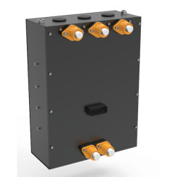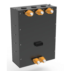
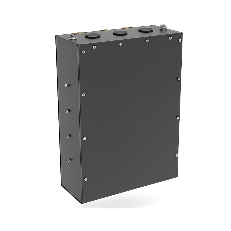


The XAP Technology MVC-100 is a liquid-cooled inverter designed for electrification projects, from prototype development to vehicle integration. It controls one 100 kW three-phase motor, one six-phase motor or two independent 50 kW three-phase motors. Live configuration, multiple position-sensor interfaces and integrated auxiliary I/O help engineering teams streamline system architecture, wiring and calibration.
The MVC-100 supports retrofit projects, electric vehicles, marine applications and industrial equipment requiring flexible motor control within an 80 to 300 V DC architecture. Its compact 425 × 350 × 177 mm enclosure and 12 kg weight make it easier to package in space-constrained installations.
XAP designed the MVC-100 to control different permanent-magnet motors and work with several position-feedback technologies: resolver, Hall sensors, sin/cos, digital SSI and digital encoders. Its Field-Oriented Control (FOC) algorithm regulates torque and speed, while the embedded calibration tool enables live mapping with three access levels: basic, standard and expert.
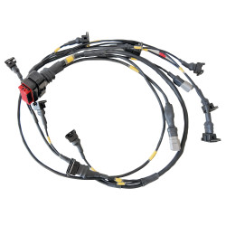
The MVC-100 also provides inputs and outputs for auxiliaries such as pumps, solenoid valves and fans. Two independent CAN-FD buses separate communication with other equipment, while the isolated USB interface supports configuration, diagnostics and firmware updates. XAP can assist with loom, connector and configuration definition to suit the project architecture.
The MVC-100 combines its power stage, motor control and I/O functions in one enclosure. XAP can help integrators define power connections, cooling, motor interfaces, CAN communication and configuration. Before power-up, the installer must validate wiring, protection devices, interlocks, CAN termination, and motor and sensor compatibility with the supplied product revision.
The power stage operates from 80 to 300 V DC, with a nominal voltage of 200 V DC. The logic supply accepts 8 to 75 V DC, subject to confirmation for the selected variant. High-current terminals provide the power connections, with recommended cable sizes of 50 to 70 mm² on the battery side and 35 to 50 mm² for the motor phases. The liquid-cooling circuit uses two Ø 10 mm push-fit ports.
| Specification | Value |
|---|---|
| Nominal voltage | 200 V DC |
| Voltage range | 80 to 300 V DC |
| Continuous power | 100 kW at 200 V |
| Continuous current | 500 A DC |
| Sustained peak current | 600 A DC for more than one minute |
| Power protection | Overcurrent, DC-bus overvoltage and undervoltage, overheating, IGBT short-circuit and sensor-fault detection |
| Battery connection | High-current stud or plate terminals; recommended cable size: 50 to 70 mm² |
| Motor phase outputs | 6 terminals: U, V, W / X, Y, Z in dual-drive configuration; recommended cable size: 35 to 50 mm² |
| Grounding | Dedicated chassis ground point |
| Specification | Value |
|---|---|
| Logic supply | 8 to 75 V DC; value to be confirmed if the variant differs |
| Communication | 2 × CAN-FD with independent bit rates; isolated USB for configuration and diagnostics |
| Inputs/outputs | 8 analogue inputs; 5 digital inputs; 2 high-side 5 A outputs with optional PWM operation |
| Supported sensors | Resolver, Hall, sin/cos, digital SSI (digital resolver) and digital encoder |
| Power-down function | Logic Power Latched: transition to a controlled state before shutdown |
| Interlocks | Dedicated inputs for high-voltage lock, doors and contactors |
| Auxiliary I/O | Logic control for pumps, solenoid valves and fans; embedded VCL function |
| Protocols and maintenance | Documented CAN frames in DBC format; diagnostics and firmware updates via USB |
| Motor configurations | 1 three-phase motor; 1 six-phase motor; 2 independent three-phase motors |
| Motor types | PMSM / BLDC permanent-magnet motors with internal or external rotors |
| Algorithm | Field-Oriented Control (FOC) for dynamic torque and speed regulation |
| Embedded calibration | Live mapping with basic, standard and expert access levels |
| Specification | Value |
|---|---|
| Cooling | Liquid (water) |
| Cooling ports | Ø 10 mm push-fit inlet and outlet ports |
| Operating temperature | –40 °C to +85 °C |
| Ingress protection | IP65 |
| Vibration and shock | Motorsport-/industrial-grade design; profiles to be defined for each project |
| Electromagnetic compatibility | Integrated filters and protection; test reports available on request |
| Overall dimensions | 425 × 350 × 177 mm |
| Weight | 12 kg |
| Pin | Signal |
|---|---|
| 1 | CAN1_Ext_P |
| 2 | CAN1_Ext_N |
| 3 | CAN2_Ext_P |
| 4 | CAN2_Ext_N |
| 5 | EXT_USB_VBUS |
| 6 | EXT_USB_D_N |
| 7 | EXT_USB_D_P |
| 8 | EXT_USB_GND |
| 9 | MOT1_HALL1 |
| 10 | MOT1_HALL2 |
| 11 | MOT1_HALL3 |
| 12 | MP2 |
| 13 | GND |
| 14 | GND |
| 15 | 5V_ANA_CPU |
| 16 | 5V_ANA_CPU |
| 17 | ANA_IN1/MOT2_HALL1 |
| 18 | ANA_IN2/MOT2_HALL2 |
| 19 | ANA_IN3/MOT2_HALL3 |
| 20 | ANA_IN4 |
| 21 | GND |
| 22 | GND |
| 23 | MP1 |
| 24 | ANA_IN5 |
| 25 | RES_EXC |
| 26 | RES_/EXC |
| 27 | COS_µC_P |
| 28 | COS_µC_N |
| 29 | SIN_µC_P |
| 30 | SIN_µC_N |
| 31 | ANA_IN6 |
| 32 | ANA_IN7 |
| 33 | ANA_IN8 |
| 34 | Alim_CMD |
| 35 | Alim_CMD |
| Reference | Description |
|---|---|
| PF0869 | MVC-100 inverter |