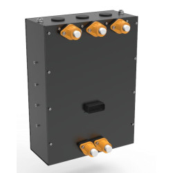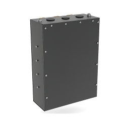
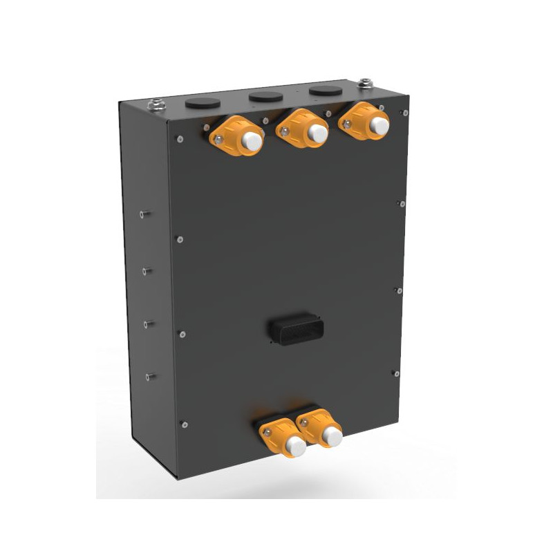


The HVC-300 from XAP Technology is a high-voltage inverter developed for motorsport programmes, prototypes and high-performance electric vehicles. From a single enclosure, it controls two independent three-phase motors or one three-phase or six-phase machine. With 300 kW of continuous power, liquid cooling and auxiliary control functions, it suits demanding architectures, while the integrated calibration tool streamlines torque and speed tuning.
Within a 12 kg enclosure, the HVC-300 combines motor control, two independent CAN-FD buses, auxiliary inputs and outputs, and several position sensor interfaces. In a twin-motor configuration, this architecture reduces the number of control units and can shorten the wiring harness, while giving integrators the freedom to build a modular powertrain.
The integrated Motor-Editor tool supports live mapping through three access levels — Basic, Standard and Expert — to assist development from prototype to series production. Additional inputs and outputs also enable the HVC-300 to control auxiliaries such as pumps, valves and fans, depending on the vehicle configuration.
The HVC-300 integrates into a 500 to 700 V high-voltage architecture. XAP can support the definition of power interfaces, signal harnesses, CAN communications and motor calibration. Before power-up, the integrator must validate cable and protection ratings, cooling, interlocks, CAN termination, and the compatibility of the motor and its sensors with the selected configuration.
The battery connects to high-current studs or plate terminals, while six phase terminals provide the U, V, W and X, Y, Z outputs in dual-drive mode. The J1 signal connector, identified by TE reference 1-776230-1, carries the two CAN networks, USB, motor position feedback, analogue inputs and the power command. CAN frames are documented in DBC format. USB supports configuration, diagnostics and firmware updates.
| Specification | Value |
|---|---|
| Nominal voltage | 600 V |
| Voltage range | 500 to 700 V |
| Continuous power | 300 kW at 600 V |
| Peak power | 340 kW |
| Continuous bus current | 500 A DC |
| Maximum continuous phase current | 1,000 Arms |
| Maximum peak phase current | 1,200 Arms for short durations |
| Power protection | Overcurrent, bus overvoltage and undervoltage, overheating, MOSFET short circuit and sensor fault detection |
| DC battery connection | High-current studs or plate terminals; recommended cable size of 50 to 70 mm² |
| Motor phase outputs | 6 terminals: U, V, W / X, Y, Z in dual-drive mode; recommended cable size of 35 to 50 mm² |
| Grounding | Dedicated chassis ground point |
| Interface | Function |
|---|---|
| Communication buses | 2 × CAN-FD with independent bit rates; frames documented in DBC format |
| USB | Isolated interface for configuration, diagnostics and firmware updates |
| Inputs | 8 analogue inputs and 5 digital inputs |
| Auxiliary outputs | 2 × 5 A high-side outputs with optional PWM control |
| Supported motor sensors | Resolver, Hall, sin/cos, digital SSI and digital encoder |
| Controlled shutdown function | Logic Power Latched to place the system in a controlled state before shutdown |
| Interlocks | Dedicated inputs for high-voltage lock, doors and contactors |
| Auxiliary control | Logic inputs and outputs for pumps, valves and fans; integrated vehicle control logic |
| Specification | Value |
|---|---|
| Drive modes | 1 three-phase motor; 1 six-phase motor; 2 independent three-phase motors |
| Machine types | PMSM / BLDC permanent-magnet motors with internal or external rotors |
| Algorithm | Flux-oriented control (FOC) for dynamic torque and speed regulation |
| Embedded calibration | Live mapping with Basic, Standard and Expert access levels |
| Specification | Value |
|---|---|
| Cooling | Liquid (water) |
| Cooling ports | Ø 10 mm push-fit inlet and outlet |
| Operating temperature | −40 °C to +85 °C |
| Ingress protection | IP65 |
| Vibration and shock | Profiles to be defined for each project |
| Electromagnetic compatibility | Integrated filters and protection; test reports available on request |
| Overall dimensions | 425 × 350 × 177 mm |
| Weight | 12 kg |
| Pin | Signal |
|---|---|
| 1 | CAN1_Ext_P |
| 2 | CAN1_Ext_N |
| 3 | CAN2_Ext_P |
| 4 | CAN2_Ext_N |
| 5 | EXT_USB_VBUS |
| 6 | EXT_USB_D_N |
| 7 | EXT_USB_D_P |
| 8 | EXT_USB_GND |
| 9 | MOT1_HALL1 |
| 10 | MOT1_HALL2 |
| 11 | MOT1_HALL3 |
| 12 | MP2 |
| 13 | GND |
| 14 | GND |
| 15 | GND |
| 16 | 5V_ANA_CPU |
| 17 | ANA_IN1/MOT2_HALL1 |
| 18 | ANA_IN2/MOT2_HALL2 |
| 19 | ANA_IN3/MOT2_HALL3 |
| 20 | ANA_IN4 |
| 21 | GND |
| 22 | GND |
| 23 | MP1 |
| 24 | ANA_IN5 |
| 25 | RES_EXC |
| 26 | RES_/EXC |
| 27 | COS_µC_P |
| 28 | COS_µC_N |
| 29 | SIN_µC_P |
| 30 | SIN_µC_N |
| 31 | ANA_IN6 |
| 32 | ANA_IN7 |
| 33 | ANA_IN8 |
| 34 | Alim_CMD |
| 35 | Alim_CMD |
| Reference | Description |
|---|---|
| PF1020 | HVC-300 INVERTER 600 V |
You might also like