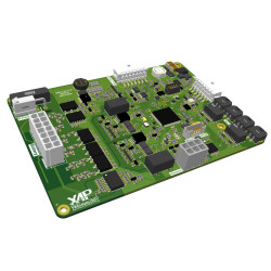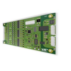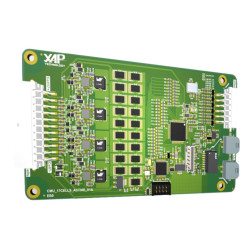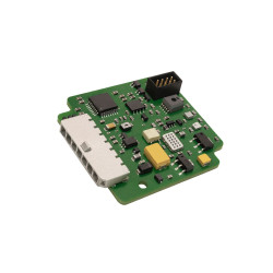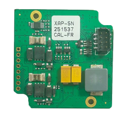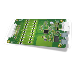
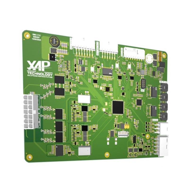

XAP Technology’s BMU-110 is the master unit of a high-voltage battery management system designed for electric vehicle conversions, motorsport and stationary energy storage projects. It centralises battery pack monitoring, controls contactors and pre-charge, calculates State of Charge (SoC), State of Energy (SoE), State of Power (SoP) and State of Health (SoH), and coordinates thermal management. Its master-slave architecture supports the integration of complex battery packs up to 900 V.
The BMU-110 brings the battery pack’s decision-making functions together on a modular platform. It processes data from the Cell Monitoring Units (CMUs), monitors high voltage and current, then sends the calculated charge and discharge limits over CAN in real time. This approach helps integrators build a coherent architecture, from individual cell monitoring through to communication with the inverter and vehicle.
XAP Technology designed this solution for traction battery systems, electric vehicle conversions, motorsport applications and stationary energy storage installations. The BMU-110 supports closed-loop control of pumps, valves, fans and heaters, integrating thermal management into the overall control of the battery pack.
The ecosystem can be expanded with an XAP Relay Board, temperature and hydrogen sensors, and an NT-Logger or 4G module for external telemetry. XAP can define the CMUs, sensors, connectors and CAN/DBC configuration to suit each project.
The BMU-110 integrates as the battery’s master controller. It receives information from the CMUs and sensors, controls the high-voltage devices and sends operating limits to other control units. XAP can help the integrator define the interfaces, CAN/DBC configuration and extensions required for the vehicle or installation architecture.
The BMU-110 accepts an isolated 7 to 75 V DC logic supply with reverse-polarity protection. It separates the vehicle and battery CAN-FD communication domains and provides USB connections for maintenance and firmware updates, together with Ethernet for diagnostics. TPL interfaces provide the connection to the CMUs.
An automated, current-limited pre-charge sequence helps secure battery pack energisation. An XAP Relay Board can extend the architecture to suit the project. Safety inputs support an emergency stop, high-voltage lock and cover sensors.
| Specification | Value |
|---|---|
| Voltage measurement ranges | 60 V / 230 V / 500 V / 900 V, automatic range selection |
| Current measurement | Up to ±500 A DC, dual path with Hall sensor + shunt or dual shunt, including dynamic coherence checking |
| Insulation test | Differential ISO_POS / ISO_NEG method based on TIDA-01513 to locate an insulation fault |
| Protection and monitoring | High-voltage interlock, HVIL, reverse-polarity protection, ESD protection and contactor weld detection |
| Logic supply | 7 to 75 V DC, isolated DC/DC conversion and reverse-polarity protection |
| Current consumption | Approximately 130 mA at 12 V in active standby |
| Function | Capability |
|---|---|
| State estimation | Real-time calculation of SoC, SoE, SoP and SoH using an electrothermal model and ageing laws |
| Power prediction | Online calculation of charge and discharge limits, published over CAN in DBC format |
| Balancing | Passive and active-hybrid strategies based on ΔV, SoC, temperature and current criteria, with thermal limiting |
| Thermal management | Closed-loop control of pumps, valves, fans and heaters |
| Pre-charge | Automated sequence with current limiting and thermal feedback |
| Shock detection | Integrated 6-axis accelerometer and gyroscope |
| External charger communication | Integrated communication via CP, PP and PE signals |
| Interface | Function |
|---|---|
| Isolated CAN-FD | Separate vehicle and battery domains |
| Service connections | USB for maintenance and secure updates; Ethernet for diagnostics |
| CMU interfaces | TPL |
| Safety inputs | Emergency stop, high-voltage lock and cover sensors |
| Supported sensors | Accelerometer/gyroscope, battery pack and busbar temperatures, hydrogen via Batt-Safe, and insulation monitoring |
| Data format | CAN frames in XAP DBC format |
| Function | Description |
|---|---|
| Event log | Persistent logging of events related to HVIL, contactors, insulation tests and pre-charge, with CRC and timestamps |
| Network security | Physical bus separation, CAN ID whitelisting and timeout strategy |
| External telemetry | NT-Logger or 4G module with read-only access over CAN |
| Specification | Value |
|---|---|
| Dimensions | Approximately 175 × 125 mm for the standalone board |
| Weight | Less than 500 g for the standalone board, without enclosure |
| Connectors | AMPSEAL, Micro-Fit and MC4 |
| Mounting | Four-point stand-off mounting; optional shielded metal enclosure |
| Ingress protection | IP65 with enclosure |
| Operating temperature | −40 °C to +85 °C |
| Reference | Description |
|---|---|
| PS0543 | BMU-110 |
You might also like