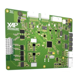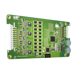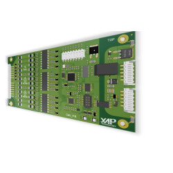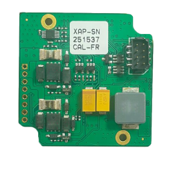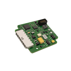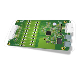
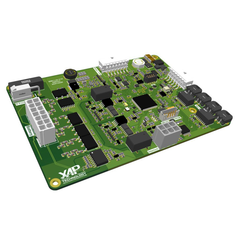

XAP Technology’s BMU-120 is a battery management unit for retrofit, motorsport and stationary storage projects. Its master-slave architecture centralises cell monitoring and controls essential pack functions, from pre-charge to thermal management. Its modular design, two isolated CAN-FD buses and electro-thermal algorithms help integrators build a scalable and coherent battery architecture.
The BMU-120 measures high voltage and current, estimates State of Charge, Energy, Power and Health, then publishes charge and discharge limits over CAN. The architecture supports 1 to 64 CMUs per pack, within the documented limit of 1,088 cells, allowing the supervision system to be matched to the number of modules required by the application.
XAP can add a relay board to extend the power control architecture. The BMU-120 controls two 500 A contactors and a pre-charge stage, manages pumps, valves, fans and heaters in closed loop, and communicates with the CMUs through a TPL interface. USB supports maintenance and firmware updates, while Ethernet provides the diagnostic link.
The BMU-120 sits at the centre of a battery architecture connecting CMUs, sensors, contactors, the charger, the inverter and thermal management devices. XAP can support the definition of interfaces, DBC-format CAN frames and project-specific accessories. Before power-up, the integrator must validate the high-voltage design, protections, interlocks, pre-charge, CAN termination and compatibility of every component.
The logic supply accepts 7 to 75 V DC through isolated DC/DC conversion with reverse-polarity protection. Current measurement uses two paths — Hall and shunt, or two shunts — with dynamic coherence checking. The BMU-120 connects the battery domain to the CMUs through TPL and to the vehicle through two isolated CAN-FD networks; USB supports maintenance and firmware updates.
| Specification | Value |
|---|---|
| High-voltage ranges | 60 V / 230 V / 500 V / 900 V, multi-range with automatic switching |
| Current measurement | Up to ±500 A DC; Hall + shunt or dual-shunt paths, with dynamic coherence checking |
| Insulation test | Differential ISO_POS / ISO_NEG method; the source documentation cites reference TIDA-01513 |
| Power protections | High-voltage interlock and HVIL, reverse-polarity protection, ESD protection and contactor weld detection |
| Logic supply | 7 to 75 V DC; isolated DC/DC conversion and reverse-polarity protection |
| Consumption | ≈130 mA at 12 V in active standby |
| Contactors and pre-charge | Control of 2 × 500 A contactors and a pre-charge stage; expandable with an XAP relay board |
| Function | Capability |
|---|---|
| State estimation | Real-time State of Charge (SoC), State of Energy (SoE), State of Power (SoP) and State of Health (SoH) calculation using an electro-thermal model and ageing laws |
| Power prediction | Charge and discharge current and power limits published over CAN in DBC format |
| Balancing | Passive and active hybrid strategies based on ΔV, SoC, temperature and current criteria, with thermal limiting |
| Pack management | 1 to 64 CMUs per pack, up to 1,088 cells; redundant Dual-Path architecture |
| Thermal management | Closed-loop control of pumps, valves, fans and heaters |
| Pre-charge sequence | Automated current-limited charging with thermal feedback |
| Interface | Function |
|---|---|
| CAN networks | 2 × isolated CAN-FD buses for the vehicle and battery domains |
| Service links | Secure USB for maintenance and firmware updates; Ethernet for diagnostics |
| CMU interfaces | TPL |
| Safety inputs | Emergency stop, high-voltage lock and cover sensors |
| Supported sensors | Pack temperature, busbar temperature, H₂ via Batt-Safe and insulation monitoring |
| Data format | Standardised CAN frames, XAP DBC |
| Specification | Value |
|---|---|
| Dimensions | ≈175 × 125 mm for the board only |
| Weight | <500 g for the board only, without housing |
| Connectors | Industrial AMPSEAL, MicroFit and MC4 connectors for high-voltage measurement and control |
| Mounting | Four-point stand-off mounting; shielded metal housing available as an option |
| Operating temperature | −40 °C to +85 °C |
| Ingress protection | IP65 with housing |
| Electromagnetic compatibility | Integrated filters and shielded layers; test reports associated with UNECE R10 / ISO 11452 available on request |
| Stated continuous operation | >13,000 h; active monitoring by Batt-Safe sensor module |
| Reference | Description |
|---|---|
| PS0575 | BMU-120 |
View the official product page and access the BMU-120 technical data sheet.
You might also like